
Fanless SBC Thermal Design for Industrial Enclosures
Plan fanless SBC thermal design from power measurement to heat spreaders, gap pads, enclosure cooling, hot-spot checks, and sustained workload validation.
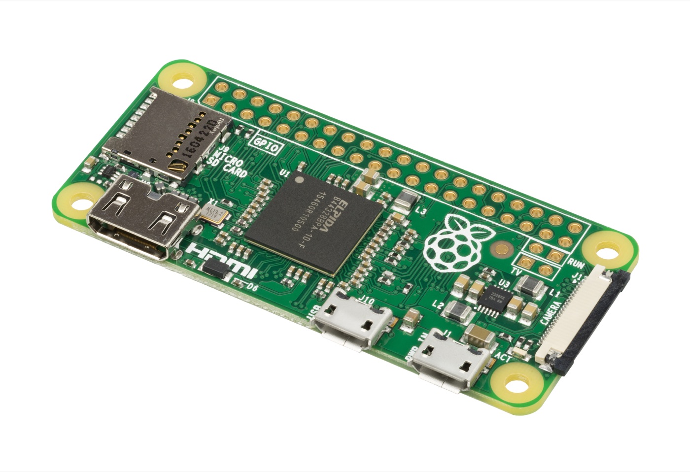
A bare SBC stays cool on the bench, then throttles after it is mounted behind a display. The processor did not change. The air around it, the available heat path, and the neighboring heat sources did.
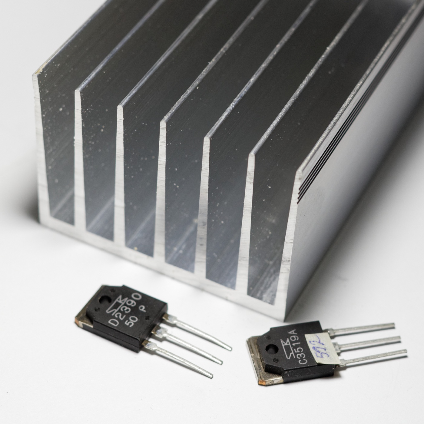
Fanless SBC thermal design is the design of that complete path: silicon to package, package to board or spreader, spreader to enclosure, and enclosure to the surroundings. A heat sink is one component in the path. It cannot compensate for a poor contact, an undersized enclosure, or an installation that blocks the intended cooling surface.
Start with the required sustained workload and maximum installation ambient. Then budget temperatures, build a mechanically repeatable path, and measure the finished assembly. The calculations below are illustrative design checks, not thermal test results for a particular SBC.
1. Build a Power Map Before Choosing a Heat Sink
Processor power is not total enclosure heat. Include memory, storage, Ethernet PHYs, radios, USB peripherals powered inside the enclosure, power-conversion losses, and display electronics. A bright backlight can materially change the panel’s thermal environment even when the application processor is lightly loaded.
Measure the relevant operating modes: idle display, normal interaction, peak sustained computation, communications bursts, storage writes, and the supported update process. Capture both short peaks and sustained demand. A transient peak may primarily affect power delivery, while a lower continuous load sets the final temperature.
| Heat source | Measurement question | Design consequence |
|---|---|---|
| SoC | What is sustained power for the real CPU/GPU/NPU mix? | Main spreader and performance budget |
| Memory and PMIC | Which parts become hot beside the SoC? | Local board temperature and airflow or conduction needs |
| Storage | Does continuous I/O raise controller temperature? | Separate contact or thermal clearance |
| Display/backlight | What happens at the required brightness? | Shared enclosure load and front-surface temperature |
| Power converter | What loss occurs at actual input voltage and load? | Additional internal heat, often away from the SoC |
Measure at a clear electrical boundary. Input power includes energy delivered to external loads; not all of it necessarily becomes heat inside the SBC enclosure. Conversely, measuring only a processor rail omits the rest of the system.
Keep the panel PC architecture in the discussion. Separating the display and compute assembly may alter both heat flow and serviceability. That choice is difficult to revisit after the enclosure tooling is committed.
2. Use a Thermal Budget, but Respect Its Assumptions
For a simplified steady-state path, allowable thermal resistance is temperature rise divided by heat flow. Suppose a hypothetical heat source dissipates 8W, the relevant ambient is 55°C, and the design sets a 90°C junction target. The total allowable junction-to-ambient resistance would be:
(90 − 55)°C / 8W = 4.375K/W.
That budget includes the entire effective path, not just the heat sink. The 90°C value is an illustrative design target, not a universal processor limit. Use the exact part’s specification and your own reliability and performance requirements.
A real SBC has multiple heat sources and parallel paths through the PCB, package, enclosure, and air. The simple calculation is useful for rejecting implausible concepts, not for certifying a multi-source assembly. Nearby hot components also mean the local ambient may differ from the room temperature.
Do not treat a datasheet’s junction-to-ambient value as a universal property of the chip. TI’s Semiconductor and IC Package Thermal Metrics explains why package thermal metrics depend on test conditions and must be interpreted carefully. A standardized test board is not your sealed product.
Work the enclosure budget separately. If a hypothetical enclosure must reject 15W while its chosen case target is 70°C in a 50°C ambient, the case-to-ambient target is approximately 1.33K/W. That does not establish a permissible touch temperature; accessible-surface limits require their own product-specific assessment.
3. Make the Mechanical Contact Repeatable
The thermal path must survive production tolerances. Check the height of the processor package, board bow, standoff stack, enclosure flatness, and fastener arrangement. A prototype held together with extra screw torque is not a controlled manufacturing process.
Thermal interface material fills microscopic gaps and, in some designs, a larger mechanical gap. Its thickness matters. Using the simplified conduction relation R = thickness / (conductivity × area), a 1mm pad with a conductivity of 3W/(m·K) over 20 × 20mm has an idealized resistance of about 0.83K/W. At 8W that represents roughly 6.7°C of rise, before contact and spreading effects.
Those figures are an example, not a material recommendation. Real pads have compression-dependent behavior, tolerances, and contact resistance. A thicker pad can solve a fit problem while making thermal performance worse. A harder pad can transfer excessive load into the package or PCB.
| Interface choice | Useful property | Check before release |
|---|---|---|
| Thin paste or phase-change layer | Low gap thickness on suitable mating surfaces | Flatness, mounting force, application process, service handling |
| Compliant gap pad | Bridges controlled assembly gaps | Compressed thickness, pressure, aging and electrical properties |
| Rigid heat spreader | Distributes heat toward a larger contact area | Flatness, mounting stress, adjacent-component clearance |
| Direct enclosure coupling | Removes an extra heat-rejection stage | Housing tolerance, isolation needs, surface temperature |
Specify the interface material and assembly method in the BOM and work instructions. “Equivalent thermal pad” is too vague when its stiffness or compressed thickness changes the contact pressure. Confirm the processor vendor’s mechanical limits before applying preload.
4. The Enclosure Must Reject Heat to Its Surroundings
A spreader can move heat away from the processor while leaving the entire enclosure too hot. Check surface area, material, finish, mounting, orientation, and the surrounding clearance. Natural convection depends on the installation; a fins-up bench arrangement may not represent a wall-mounted panel.
Do not assume aluminum automatically solves the problem. A metal rear cover helps only if heat reaches it and it has a useful path to the surroundings. A decorative cover isolated from the board by air and plastic standoffs may contribute little to the main conduction path.
For sealed products, avoid treating internal air as an unlimited sink. It warms up. Heat still has to cross the enclosure wall and leave the outside surface. For ventilated products, account for dust, blockage, and the actual mounting clearances rather than assuming permanent laboratory airflow.
Include external heating where relevant. Direct sun, a nearby power supply, or a cabinet wall hotter than the surrounding room can invalidate an ambient assumption. State what “ambient” means in the product requirement and where it is measured during testing.
If the thermal budget still does not close, revisit sustained power, enclosure size, or mounting before selecting a more expensive pad. Interface improvements cannot remove a fundamental case-to-environment bottleneck.
5. Measure Hot Spots and Delivered Performance Together
Instrument a representative final assembly. Record external ambient, internal air where useful, processor telemetry, relevant component temperatures, enclosure temperature, and workload performance. Board telemetry is useful but may not report every hot component or exactly match the temperature definition in a component specification.
Thermocouples need careful placement and attachment. Thermal cameras need appropriate emissivity settings and attention to reflective metal surfaces. A bright-looking or cool-looking patch on bare aluminum is not automatically its true temperature.
Run until the temperatures are sufficiently stable for the test’s stated criterion. There is no universal soak time that proves equilibrium for every enclosure. A small board and a heavy metal housing can settle on different timescales, so preserve the temperature-versus-time trace.
Record frame rate, response latency, CPU/GPU frequencies where accessible, storage throughput, and error counters alongside temperature. A system can avoid a thermal shutdown by throttling so heavily that it no longer performs its job. The acceptance criterion must cover useful work, not just survival.
The RK3568 and RK3588 illustrate why processor selection and thermal design cannot be separated: different workload capabilities bring different integration demands. The model name alone does not tell you the sustained performance inside your housing.
Repeat the required conditions with the display at its specified brightness, storage active, and radios or other peripherals in representative modes. Separate exploratory worst-case stress from the defined product workload, and report both honestly if both are tested.
6. Qualify the Assembly and Preserve It in Production
Test more than one hand-built sample when assessing tolerance sensitivity. Include realistic variation in pad thickness, assembly fit, and component population. Do not intentionally exceed mechanical limits to create a nominal “worst case”; work from controlled drawing tolerances and supplier data.
Add cold starts and temperature transitions where the installation requires them. The thermal path also has mechanical consequences: expansion, repeated service disassembly, and interface-material aging can change contact over time. Select the appropriate qualification procedures with the product’s reliability team.
Tie the results to industrial board qualification. Preserve the board revision, enclosure drawing, interface material, fastener specification, software build, test orientation, and workload. A cooling result without that configuration is hard to reproduce after a supplier substitution.
Production inspection should check the parts of the thermal path that can be assembled incorrectly: missing pads, protective liners left in place, displaced spreaders, incorrect screws, and connectors preventing the enclosure from seating. Define a practical test or inspection rather than expecting the final functional test to catch every contact problem.
The finished design should have a simple answer to three questions: where does the heat go, what limits the sustained workload, and what variation has been validated? If those answers rely on an open enclosure or an unusually careful prototype assembly, the fanless design is not finished yet.
Frequently Asked Questions
Can an industrial SBC run without a fan?
Yes, if its measured heat load can pass through a suitable thermal path to the environment while meeting component, enclosure, and application-performance limits. Fanless does not mean heatsink-free or enclosure-independent.
Can I size an SBC heatsink from processor TDP alone?
No. Use the relevant processor power conditions and measure the actual application. Include other heat sources such as memory, storage, power conversion, radios, and a display backlight when they contribute to the enclosure load.
Is a thicker thermal pad better for cooling?
Not inherently. A thicker pad can bridge a larger gap but adds conduction resistance for the same material and area. Select thickness and compression from mechanical tolerances, contact requirements, and the material’s specified behavior.