
eMMC vs UFS vs NVMe for Embedded Systems: Beyond Peak Speed
Compare eMMC, UFS, and NVMe for embedded systems by boot support, latency, endurance, power loss, heat, and the storage workload your product actually runs.
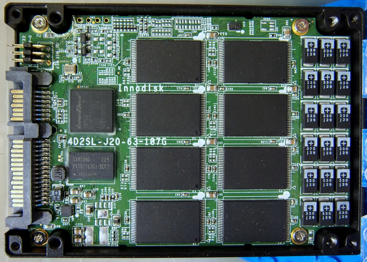
A storage device can post an excellent sequential-read result and still make a panel unpleasant to use. The operator notices a delayed alarm-history query, not the drive’s best transfer rate on an empty filesystem.
The eMMC vs UFS vs NVMe decision starts with three constraints: what the processor can boot, what the application reads and writes, and what happens when power disappears. eMMC is often a practical fit for modest fixed-function products. UFS is worth evaluating when a supported platform needs faster compact managed storage. PCIe NVMe suits heavier storage workloads when the board can afford its lanes, power, and cooling.
None of those interfaces establishes endurance, industrial temperature qualification, or safe power-loss behavior by itself. Those belong to the exact device and the assembled product.
1. Separate the Interface from the Package
eMMC and UFS combine flash memory and a controller in a managed storage device, commonly soldered to the board. The host does not directly manage raw NAND cells, but it still depends on the device’s firmware, endurance, and recovery behavior.
eMMC uses a parallel host interface. UFS uses a serial interface with separate transmit and receive paths; implementing it requires a compatible host and board design. KIOXIA’s UFS technical overview describes its integrated controller and serial interface. A processor’s eMMC support does not imply UFS support.
NVMe defines a storage protocol. For the local SBC storage discussed here, the usual transport is PCIe. M.2, in contrast, is a physical module and connector specification: an M.2 socket’s appearance does not prove it carries the required PCIe lanes or supports booting an NVMe drive. Check the schematic and firmware support.
| Question | eMMC | UFS | PCIe NVMe |
|---|---|---|---|
| Typical board integration | Soldered managed-flash package | Soldered managed-flash package | Often an M.2 module; other packages exist |
| Host requirement | Compatible MMC controller | UFS host and PHY | PCIe root complex plus NVMe software |
| Likely design attraction | Compact implementation for moderate I/O | Higher-performance compact storage | Capacity, concurrency, replaceable drive options |
| First integration check | Boot mode and approved part | SoC, PHY, routing, boot support | Lane allocation, reset, power, boot support |
| Endurance or power-loss guarantee | Model-specific | Model-specific | Model-specific |
Do not put one universal MB/s figure beside each interface. Device generation, NAND configuration, capacity, link mode, queue depth, and software all matter. Micron’s embedded storage comparison is useful context for the architectural differences; results from one platform are not a guarantee for another.
2. Check the Boot Chain Before Ordering the Drive
An operating system that can mount an NVMe filesystem after startup is not necessarily able to boot from that drive. The early boot path may still need eMMC, SPI flash, or another supported medium for firmware and bootloader stages.
Ask the supplier to identify every storage device involved in cold boot, recovery, and factory provisioning. Then ask what happens if the main data drive is missing or unreadable. A gateway with separate boot and data storage should still offer a defined recovery path; it should not sit indefinitely at a bootloader prompt.
Android brings additional integration work. Partition layout, verified boot, encryption, recovery, and the selected update mechanism must match the BSP. A drive recognized by a generic Linux image does not prove that the production Android image can provision, update, and recover it correctly.
Capacity planning must include that partition layout. Do not subtract the application APK from nominal drive capacity and treat the remainder as available data space. OS partitions, update staging or snapshots where used, logs, user data, filesystem overhead, and reserved free space all consume capacity. A/B and virtual A/B implementations differ; budget the actual BSP rather than assuming every update requires two complete copies of everything.
For custom Android boards, make the boot and recovery diagram a design deliverable. It catches a missing recovery path earlier than a storage benchmark does.
3. Test the I/O Pattern Your Product Produces
A signage player copying large media files and a controller committing small database transactions stress storage differently. Sequential throughput matters to the former. Tail latency and synchronization behavior may dominate the latter.
Build the test around application operations: boot to a usable screen, open the largest history view, write an alarm record, rotate a log, download an update, and resume after a power interruption. Record the workload, fill level, temperature, encryption state, and firmware revision so the result can be repeated.
| Workload | Useful measurement | Easy mistake |
|---|---|---|
| Media loading | Sustained read rate and application ready time | Testing only a short cached file |
| Database commits | Commit latency distribution, including slow cases | Reporting average throughput alone |
| Logging plus UI | UI response while writes continue | Testing each task in isolation |
| Update workflow | Download, verification, installation, recovery | Timing only the file copy |
| Continuous recording | Sustained writes after caches settle | Using an empty-drive burst result |
Run on a disposable test dataset, not a production unit carrying customer records. Storage stress tests can erase data or consume a meaningful amount of write endurance if configured carelessly.
The full system matters. A drive may slow as its temperature rises or as internal housekeeping increases under a sustained workload. Filesystem cache can also make a second read look far faster than the first. Report both the conditions and the symptom you are trying to prevent.
If changing Android RAM capacity changes the result dramatically, distinguish a larger cache from faster underlying storage. Both can help the product, but they solve different problems.
4. Convert Logging into a Lifetime Write Budget
Start with host writes rather than an optimistic NAND-cycle estimate. Include database journals, filesystem metadata, application logs, cached downloads, update files, and repeated writes of unchanged state.
For an illustrative product writing 10GB per day over ten years, the host-write total is approximately:
10GB/day × 365 days/year × 10 years = 36.5TB.
This is a planning example, not a measured workload or recommended drive rating. Add a justified allowance for growth and workload uncertainty. Then compare the result with the manufacturer’s endurance specification under its stated conditions.
Do not automatically multiply the host-write estimate by write amplification and compare that enlarged figure with a host-TBW rating. That mixes two different accounting boundaries. NAND writes can exceed host writes internally, but a rating expressed as host terabytes written already uses the host boundary under a specified test workload. Ask what the quoted number actually means.
Small software changes can be more valuable than changing interfaces. Batch noncritical telemetry, rotate logs, bound caches, and avoid rewriting a complete configuration file for every tiny state change. Do not sacrifice necessary audit records merely to reduce writes; define their retention and durability requirements first.
Monitor the device’s available health information where supported, but treat it as a diagnostic indicator rather than an exact remaining-life clock. Archive the meaning of each field for the chosen model and firmware. A replacement component may report health differently even if it has the same capacity.
5. Pulling Power Tests the Whole Storage Stack
“Industrial flash” and “NVMe” are not synonyms for power-loss protection. A device may protect some internal metadata without guaranteeing that every recent application write survives. Application buffers, OS caches, drive caches, and the flash translation layer are separate parts of the path.
Define the allowed loss at the application level. Losing the last few noncritical telemetry samples may be acceptable; corrupting a calibration record may not be. Then verify that the application’s synchronization and transactional behavior match that requirement.
Use a controlled interruption fixture on sacrificial units. Exercise interruptions during database commits, log rotation, boot, and the supported update workflow. Inspect both filesystem recovery and application-level consistency afterwards. A clean mount is not proof that the business record is correct.
Include brownout and repeated interrupted starts when those can occur in the installation. A bench power switch does not reproduce every slow or noisy supply failure. The power design, reset thresholds, and storage behavior have to be considered together.
6. Include Heat, Mechanics, and Replacement Control
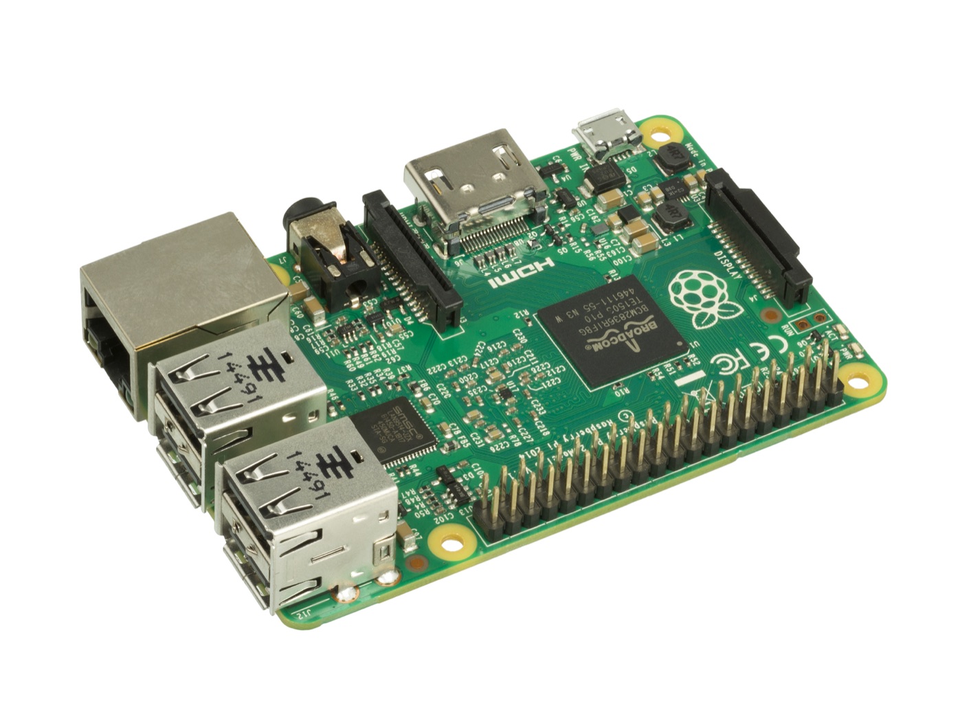
An M.2 drive needs physical clearance, retention, and a credible heat path. In a sealed enclosure, the drive sits beside other heat sources rather than on an open benchmark bench. Fanless enclosure cooling should include the storage controller, not only the SoC.
Soldered storage avoids a removable connector but makes field replacement difficult. Socketed storage can simplify servicing while adding assembly and vibration considerations. Neither choice is inherently superior; the service model should decide.
Freeze the full part number and qualified firmware revision where the supplier allows it. “Equivalent 64GB storage” is not enough for a production substitution. A different internal controller or NAND generation can alter timing, startup current, endurance reporting, and recovery behavior without changing the capacity label.
The release package should contain the boot map, capacity budget, measured workload, endurance assumptions, interruption results, and approved substitutions. Purchasing then has something concrete to preserve when a part becomes unavailable.
Keep at least one representative unit for later regression work, with its original storage identity recorded. When a supplier changes the drive firmware or managed-flash package, rerun the sensitive operations on both configurations. A successful installation of the factory image checks provisioning, but does not establish that the new part handles a nearly full filesystem or repeated interrupted database commits like the old one.
Choose eMMC when it meets those requirements with the simplest supported implementation. Choose UFS when the platform supports it and its measured behavior solves a real bottleneck. Choose NVMe when its capacity, concurrency, or serviceability justifies the additional integration. The right drive is the one that still behaves predictably in a warm enclosure with a used filesystem—not just the one with the largest number on its datasheet.
Frequently Asked Questions
Is NVMe always better than eMMC for an embedded SBC?
No. NVMe is attractive for demanding I/O and higher capacities, but its PCIe, boot, power, thermal, and mechanical requirements may not suit a small fixed-function product. Compare sustained workload behavior and system cost, not only peak transfer rate.
Can UFS replace eMMC on the same PCB footprint?
Not as a general drop-in substitution. UFS uses a different host interface and requires compatible processor hardware, routing, power, boot firmware, and software support. Package details must also be checked.
Does an NVMe SSD guarantee power-loss protection?
No. Power-loss behavior is device-specific. Obtain the exact model’s guarantees and validate interruption during real application writes and updates; the NVMe interface alone does not guarantee preservation of volatile data.